AC/DC Calc
measurement guides
AC RMS to peak voltage: derive the sine-wave conversion
Understand the square-root-of-two factor, its waveform assumption, and how peak voltage enters a rectifier model.
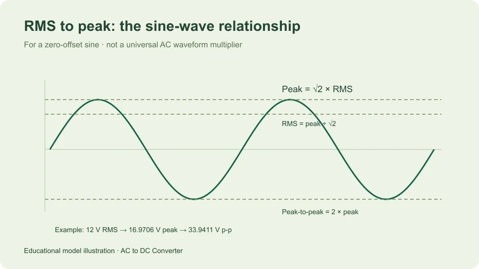
For a sinusoidal voltage with no DC offset, peak voltage equals RMS voltage multiplied by the square root of two. A 12 V RMS sine therefore has a positive peak of approximately 16.9706 V. Its negative peak is the same magnitude with opposite sign, and its peak-to-peak span is approximately 33.9411 V.
The waveform qualification is part of the formula. The factor √2 is not a universal multiplier for everything described as AC. It follows from the way a sine varies over time. Understanding that derivation makes it easier to use an AC-to-DC calculator correctly and to recognize when a different waveform needs a different treatment.
What RMS actually calculates
RMS stands for root mean square. The operation has a specific order: square the instantaneous voltage, average those squared values over the relevant time interval, then take the square root. Squaring ensures that a negative half-cycle contributes positively rather than canceling the positive half-cycle.
For a periodic waveform v(t) with period T, write Vrms = √[(1/T) ∫₀ᵀ v(t)² dt]. This definition supplies a mathematical value for a known waveform. It does not require that the waveform be a sine, although the resulting expression depends on its shape.
By comparison, the signed arithmetic average of a symmetric sine is zero. Taking the average first and then squaring would therefore give a completely different result. The distinction in operation order is why RMS cannot be replaced with “average AC voltage” without explaining exactly what that phrase means.
Derive the sine-wave factor
Let the sine voltage be v(t) = Vm sin(ωt), where Vm is its peak magnitude. Squaring gives Vm² sin²(ωt). The mean of sin² over a complete cycle is one half. Therefore the mean squared voltage is Vm²/2.
Taking the positive square root gives Vrms = Vm/√2. Rearranging gives Vm = √2 Vrms. Numerically, √2 is approximately 1.41421356, while its reciprocal is approximately 0.70710678. Those factors connect peak magnitude and RMS for this waveform.
The derivation also reveals the limits. A sine with a DC offset has an additional contribution to its total RMS value. A waveform with a different shape has a different mean of its squared normalized shape. Neither case can be handled by silently applying the zero-offset sine factor to an unrelated measurement.
Work through ordinary numerical examples
At 6 V RMS, multiplying by √2 gives approximately 8.4853 V peak. At 12 V RMS the result is approximately 16.9706 V peak. At 24 V RMS it is approximately 33.9411 V peak. Doubling the RMS value doubles the peak because this relationship is linear for a fixed sine shape.
The reverse calculation divides a known sine peak by √2. A 10 V peak sine has approximately 7.0711 V RMS. A 20 V peak sine has approximately 14.1421 V RMS. Keeping the direction explicit helps avoid using the reciprocal factor by accident.
These are mathematical examples, not measurements or recommended circuit inputs. The calculator’s numeric precision lets you reproduce the arithmetic, but it does not establish the calibration, tolerance, or real waveform shape of a source described with the same nominal number.
Peak is not peak-to-peak
For a symmetric sine centered on zero, the waveform runs from −Vm to +Vm. Its peak-to-peak value is therefore 2Vm. Starting from RMS, Vpp = 2√2 Vrms. Starting from peak-to-peak, Vrms = Vpp/(2√2).
Suppose a waveform is described as 20 V peak-to-peak. Its positive peak magnitude is 10 V, so its RMS value is approximately 7.0711 V. Entering 20 V as an RMS input would imply a much larger sine, with a peak of approximately 28.2843 V.
This naming distinction matters before any rectifier formula is applied. An input entered with the wrong convention can still produce a plausible-looking result. The calculator cannot recover the intended convention from the number alone. Labels such as V RMS, V peak, and V p-p prevent that ambiguity.
Compare other waveform shapes
A symmetric square waveform switching between +A and −A has a squared value of A² at all times, apart from the transition instants. Its RMS is therefore A. Its peak-to-RMS ratio is one, rather than √2.
A symmetric triangular waveform between the same limits spends more time at smaller magnitudes. Integrating the square of its linear ramp gives a mean square of A²/3, so its RMS is A/√3. Its peak-to-RMS ratio is √3.
These examples follow directly from the RMS definition and show why waveform shape matters. They are not extra modes hidden inside the site’s rectifier calculator. That calculator explicitly takes a sinusoidal RMS input. If the known source is square, triangular, pulsed, or distorted, do not relabel it as a sine merely to use the available input box.
Understand crest factor
The ratio of peak magnitude to RMS is called crest factor. For the zero-offset sine just derived, it is √2. A waveform containing short high peaks can have a larger crest factor than a sine with the same RMS value.
Tektronix’s AC power measurement application note discusses crest factor and the need to distinguish RMS and peak. The important practical point here is simply that knowing RMS does not establish the peak unless the waveform information is sufficient.
When a source specification supplies both RMS and waveform requirements, keep them together. If a measurement is described as true RMS, that describes the instrument’s measurement method within its specifications; it does not prove that the measured waveform has a particular crest factor. The instrument and the waveform are separate parts of the description.
Add a DC offset carefully
Consider v(t) = D + A sin(ωt). Over a full cycle, the cross term averages to zero because the mean of the sine is zero. The total mean square becomes D² + A²/2, giving total RMS = √(D² + A²/2).
If D is 3 V and A is 4 V, total RMS is √17, approximately 4.1231 V. Yet the upper extreme is 7 V and the lower extreme is −1 V. Multiplying 4.1231 V by √2 would not recover either extreme because the zero-offset sine assumption no longer holds.
This example also distinguishes the RMS of the varying component from the total RMS including offset. The site’s main calculator is not an arbitrary-offset waveform converter. Its input convention stays deliberately narrower so that the downstream rectifier formulas have a defined meaning.
Connect the sine peak to rectifier estimates
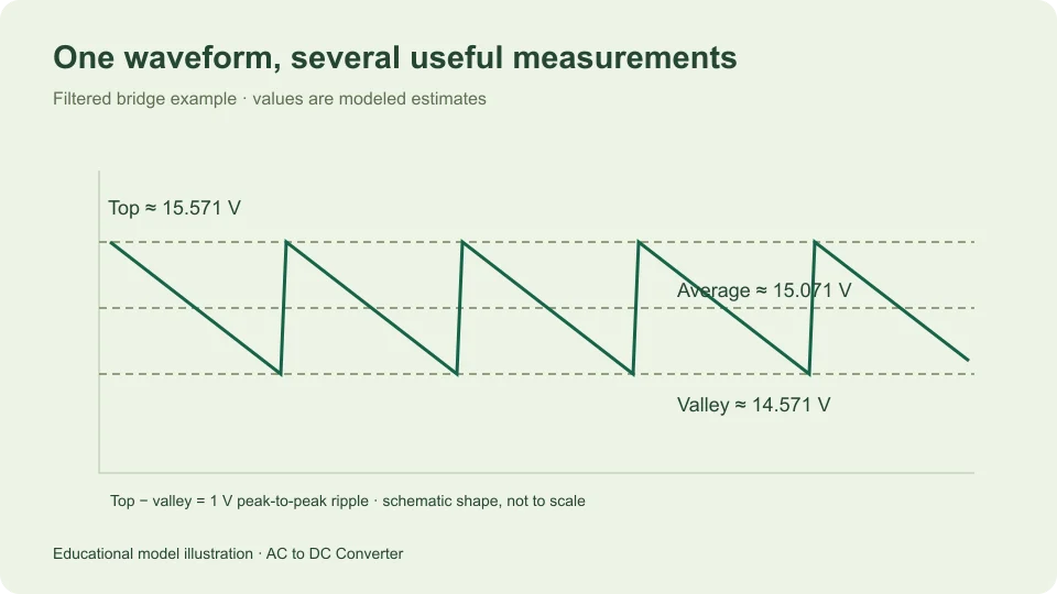
Peak voltage is a useful intermediate quantity in a capacitor-filtered bridge approximation. With a sinusoidal input, begin with Vm = √2 Vrms. The simplified bridge model subtracts two assumed forward diode drops to estimate the top available to the smoothing capacitor.
For 12 V RMS and an illustrative 0.7 V per diode, the available top is approximately 16.9706 − 1.4 = 15.5706 V. This is not yet the modeled loaded average. The filter discharges between charging peaks, so the average and valley require the load, frequency, and capacitance assumptions too.
With 50 Hz, 0.1 A constant load, and 1,000 µF, the site’s ripple approximation gives 1 V p-p. The average estimate becomes approximately 15.0706 V. Thus converting RMS to peak is one step within the model, rather than a complete prediction of regulated DC output.
Check the conversion with discrete samples
The integral definition also has a useful numerical counterpart. Imagine one cycle represented by equally spaced voltage samples. Square each sample, add the squares, divide by the number of samples, and take the square root. With enough samples and a suitable representation of the complete cycle, the result approaches the analytical RMS value.
For a simple illustration, sample an ideal sine at phase angles of 0°, 90°, 180°, and 270°. Its normalized values are 0, 1, 0, and −1. Their squares average to 1/2, so this particular symmetric set recovers the sine’s RMS factor. That convenient example is not a general guarantee that four samples can characterize arbitrary signals. Different waveforms and sampling choices need more information.
Another arithmetic check is to square the calculated RMS and compare it with half the peak squared. If the sine peak is 10 V, half its squared magnitude is 50 V². Squaring the corresponding 7.0711 V RMS value gives approximately the same result, with the small difference caused by rounding. This checks the algebra and direction of conversion without introducing a new physical assumption.
Keep the unit unchanged
RMS and peak identify how voltage is summarized; both are still expressed in volts. Multiplying by √2 does not convert volts into another physical unit. If a reading is supplied in millivolts, you may perform the RMS-to-peak multiplication in millivolts and then convert the scale separately.
For instance, a 500 mV RMS sine has approximately 707.107 mV peak, equal to approximately 0.707107 V peak. Keeping the scale conversion separate from the waveform conversion makes both steps easy to check and helps avoid a factor-of-one-thousand error.
Check the assumptions before using the factor
First identify the waveform and measurement convention. A sinusoidal RMS input supports the √2 relation; a peak input or peak-to-peak input needs rearrangement before it goes into an RMS field. A total RMS value with an offset needs additional information about its components.
Then distinguish numerical conversion from physical interpretation. Multiplying volts RMS by √2 changes the mathematical description of a known sine. It does not change the source, add a rectifier, account for losses, or determine available current.
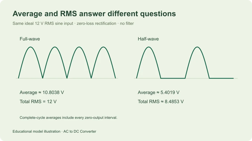
Use the AC to DC calculator when you have the input convention and circuit assumptions it requires. The rectifier average versus RMS guide explains the next distinction: after rectification, the waveform’s average and RMS can still be different even when every point on the output is nonnegative.
Filed under measurement guides