AC/DC Calc
capacitor filtering · component behavior
Capacitor ESR and ripple current: two different limits
Separate charge-storage ripple from resistive voltage changes and ripple-current heating.
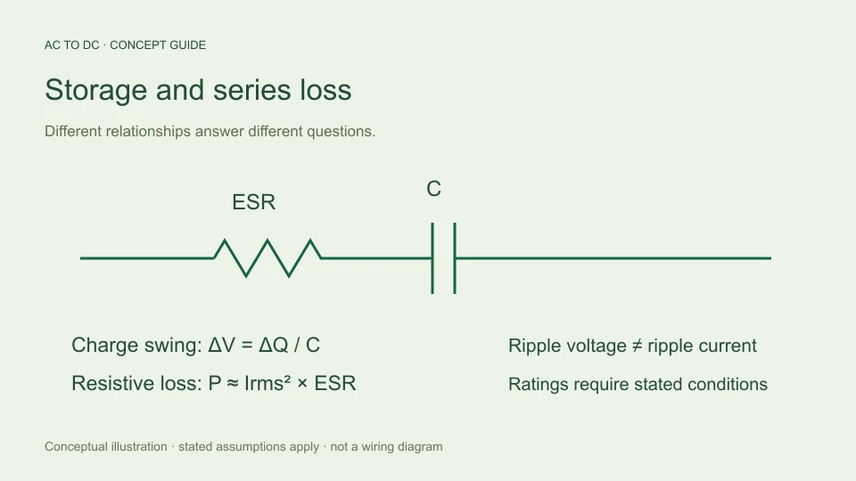
A capacitor value in microfarads cannot describe everything a reservoir capacitor does in a rectifier circuit. The ideal capacitance determines how stored charge changes its voltage. Equivalent series resistance, usually called ESR, represents a different kind of behavior: current through the loss model creates a resistive voltage component and dissipates power.
Ripple-current capability is different again. It is a component operating specification associated with an alternating current waveform and stated conditions. A voltage-ripple estimate does not automatically calculate that current or establish that a component can tolerate it. Separating these quantities helps explain both what a simple AC to DC calculator can answer and what information a more complete component analysis needs.
Start with an ideal capacitor
The ideal capacitor relation is i = C dv/dt. If current is approximately constant over a discharge interval, voltage changes linearly with slope I/C. Multiplying that slope by the interval gives ΔV = IΔt/C.
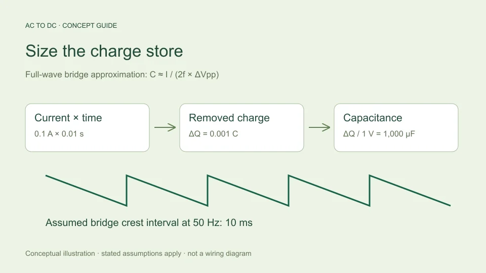
In a full-wave bridge reservoir model, using the crest-to-crest interval 1/(2f) gives the familiar estimate ΔVpp ≈ I/(2fC). This is a charge-storage voltage swing. It would exist even if the capacitor’s ESR were zero because the load removes stored charge between charging crests.
For a hypothetical 0.1 A load, 50 Hz input, and 1,000 µF, this part of ripple is 1 V peak-to-peak. The result says nothing by itself about ESR, the narrow charging-current waveform, or the capacitor’s internal temperature. Those require additional information.
Add an equivalent series resistance
A simple capacitor loss model places a resistance in series with the ideal capacitance. If instantaneous current through that resistance is i, its instantaneous voltage contribution is i × ESR. This term responds to current, whereas the ideal capacitor voltage responds to accumulated charge.
For an illustrative ESR of 0.1 Ω, a 0.1 A current would produce a 0.01 V resistive contribution. A hypothetical 1 A current at another instant would produce 0.1 V using the same fixed-resistance model. These examples are arithmetic demonstrations, not typical values assigned to an unspecified capacitor.
The terminal waveform can therefore include both gradual charge-related change and faster current-related features. Simply adding one fixed “ESR voltage” to the entire cycle would usually miss the fact that current changes in magnitude and may change direction between charging and discharging intervals.
Understand why current is not a steady load number
Between source crests, the reservoir capacitor can deliver current to the load. During charging intervals, the source replaces charge removed earlier while also serving the load. The capacitor’s own current is the difference between the current entering its node and the load current.
In a repeating steady state, the capacitor cannot accumulate charge indefinitely. Its net charge change over a complete cycle must be zero. That does not mean its current is zero at every instant. Positive charging current and negative discharging current can balance in area while producing substantial alternating current.
This distinction explains why entering DC load current into a ripple formula is not the same as calculating capacitor RMS ripple current. The latter depends on the complete current waveform, including charging intervals that the simple reservoir approximation does not solve.
Derive the resistive heating relationship
For an ideal resistance R, instantaneous dissipation is i²R. Averaging over a period gives P = R × mean(i²). Since RMS current is the square root of mean(i²), the same expression becomes P = Irms²R.
Using ESR as a simplified effective resistance gives the familiar illustrative loss relationship P ≈ Iripple,rms² × ESR. Its usefulness depends on treating the resistance appropriately for the waveform and conditions. A complicated waveform can contain multiple frequency components, for which a single fixed ESR is a further simplification.
The mathematical consequence is clear: doubling RMS current while holding resistance fixed multiplies this modeled dissipation by four. That is very different from the linear dependence of an instantaneous resistive voltage on current. Confusing the two relationships can hide why current waveform details matter to heating.
Compare two waveforms with equal average charge
Consider a deliberately simplified pulse example. A 1 A current flowing for one tenth of a cycle and zero for the remainder has an average of 0.1 A. Its RMS value is √(1² × 0.1), approximately 0.316 A.
A continuous 0.1 A current has the same 0.1 A average but an RMS value of 0.1 A. Through the same resistance, the first waveform’s mean squared current is ten times larger. This example is not a capacitor-current prediction because a reservoir capacitor also has discharge current; it isolates the reason that equal averages do not establish equal resistive heating.
The practical lesson is to ask which current convention a specification or equation requires. “Current” without an average, RMS, peak, or waveform description is often incomplete information in a rectifier-filter discussion.
Read ratings with their stated conditions
TDK’s aluminum electrolytic capacitor technical information discusses frequency and temperature dependence of ripple-current capability and the role of heating in useful life. A data-sheet ripple-current number belongs to its specified conditions rather than acting as a universal limit independent of context.
Likewise, a quoted ESR should not automatically be assumed constant for every frequency and temperature. Actual device documentation provides the relevant definitions, test frequencies, correction factors, and operating boundaries for that series.
This guide does not turn those manufacturer-specific details into a generic selection rule. Its purpose is to explain why the data must be read before a part is assessed. A microfarad value, a voltage marking, and one headline ripple-current number do not alone describe every aspect of the intended operating condition.
Separate temperature rise from power dissipation
Even a credible estimate of internal loss in watts is not yet a temperature calculation. Temperature depends on how heat is transferred to the surroundings, the ambient environment, construction, mounting, and operating history. Those factors are not contained in the equation Irms² × ESR.
For example, an illustrative 0.5 A RMS current and 0.08 Ω fixed ESR give 0.02 W in the loss model. That arithmetic is straightforward. It does not tell you an internal temperature rise without a suitable thermal model and justified parameters. Supplying an invented thermal resistance would create an apparent answer unsupported by the available information.
Keeping the questions separate makes the reasoning more precise: first estimate or obtain the waveform, then evaluate losses with suitable component data, then assess temperature and operating limits using an appropriate method.
Avoid mixing reservoir and regulator capacitors
A reservoir capacitor after a bridge and a capacitor at a regulator output may have different roles. The latter may participate in a feedback system, so its properties can affect behavior beyond the simple charge-storage picture used here.
Analog Devices’ explanation of LDO bypass-capacitor choices discusses how output capacitance and ESR can relate to regulator stability and transient response. That is a separate analysis from estimating bridge reservoir ripple.
Consequently, a broad instruction such as “always use the lowest ESR” skips the circuit-specific question. The relevant specifications must match the actual device and location. A calculator designed around an ideal reservoir capacitor should not imply that it has also verified a downstream regulator’s capacitor requirements.
Know what the site’s ripple output excludes
The AC to DC calculator reports the charge-balance estimate I/(2fC) for its filtered bridge mode. It does not ask for ESR and does not calculate capacitor RMS current. Its output therefore should be read as approximate charge-storage ripple under the stated assumptions.
The calculator also rejects ripple above 20% of available peak as a chosen guardrail for its small-ripple model. Passing that check does not establish acceptable heating, life, voltage rating, or transient performance. Those topics are outside the model even when the displayed ripple is small.
For a more detailed study, retain the simple estimate as a useful baseline, then add only the additional model elements supported by evidence. A baseline and a fuller circuit analysis can complement one another when their scope is labeled clearly.
Build a clear component-analysis record
Record capacitance and its relevant tolerance, the voltage-ripple convention, the assumed or modeled capacitor-current waveform, the RMS calculation, and the ESR conditions used for loss estimation. Keep manufacturer operating limits and thermal assumptions in separate fields rather than burying them in one result.
For an educational comparison, explicitly mark hypothetical numbers as hypothetical. For an actual component assessment, use the correct series documentation and operating conditions. The distinction prevents an illustrative example from being mistaken for a component recommendation.
The central habit is simple: stored charge explains one part of voltage ripple; series loss explains another part and contributes heating; a ripple-current specification describes permitted operation under stated conditions. Each contributes useful information, but none is a substitute for the others.
Ask a more precise question when comparing capacitors
If two hypothetical capacitors have the same nominal capacitance but different ESR, the ideal charge-balance model predicts the same storage-related discharge swing when all other assumptions are fixed. The resistive contribution and modeled losses can differ. This does not make either component universally preferable because actual suitability also depends on operating limits and the circuit’s behavior.
Conversely, two components with the same quoted ESR at one test frequency need not have the same capacitance or the same data over every relevant condition. Treating one shared number as a complete equivalence discards information that may matter to the application.
A useful comparison table therefore has separate columns for capacitance, ESR definition and conditions, ripple-current rating and conditions, voltage limits, and the evidence supporting thermal assessment. Leaving an unknown field visibly unknown is more informative than filling it with a familiar rule of thumb. It shows which part of the comparison is established and which part still requires data.
Filed under capacitor filtering component behavior