AC/DC Calc
component models · rectifier basics
Diode Forward Voltage Drop: Why the Calculator Needs an Assumption
Understand per-diode versus bridge drop, current and temperature dependence, and the limitations of a fixed-drop rectifier estimate.
A diode forward-voltage setting is an assumption about one component under an intended operating condition. It is not a universal constant that every rectifier shares. The setting is useful because it makes a simplified model more explicit, but its convenience can become misleading when a default number is treated as a guaranteed physical property.
The AC to DC calculator uses a fixed forward drop per conducting diode in its capacitor-filtered bridge model. It does not apply that input to the ideal unfiltered modes, which deliberately assume zero-loss diodes. This guide explains what the setting changes, how to interpret it, and where a single fixed number stops representing actual device behavior.
Forward voltage is tied to operating conditions
A diode’s forward voltage is part of its current-voltage characteristic. Changing current changes its operating point. Temperature also affects the characteristic. A datasheet value without its associated current, temperature, and test conditions is therefore an incomplete description.
Toshiba’s rectifier-diode forward-characteristic lesson explicitly describes dependence on current and temperature, including the different temperature behavior possible in low-current and high-current regions. The useful lesson for a calculator is to avoid turning a condition-dependent characteristic into an unexplained universal drop.
For an educational estimate, a fixed value can still be appropriate if it is clearly labeled. It lets the user explore how an assumed loss changes the available voltage. The result should retain that assumption rather than presenting the output as though a particular physical diode had been fully modeled across its entire waveform.
A bridge has two conducting diodes in its path
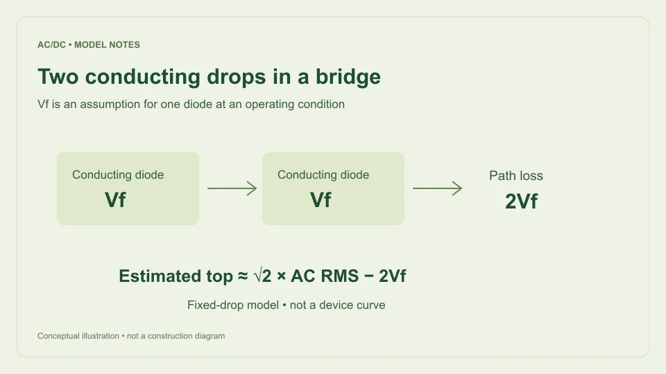
In a full-wave bridge, the output current path includes two diodes during each conducting half-cycle. The opposite pair conducts when input polarity reverses. Under a fixed-drop model, the conducting path therefore loses twice the assumed per-diode forward voltage.
The filtered calculator estimates available top voltage as Vtop ≈ max(0, √2 Vrms − 2Vf). If the per-diode input is 0.7 V, the assumed pair loss is 1.4 V. If it is 0.5 V, the assumed pair loss is 1.0 V. Those values are mathematical inputs to the model, not claims about a specific part.
The field label matters. Entering a total bridge drop in a field that expects one diode’s drop would double-count the loss. Conversely, subtracting only one drop from a bridge model would omit one part of its assumed conducting path. Keep “per diode” and “total path” visible whenever the number is copied into another worksheet.
Why 0.7 V is only an illustrative default
The default provides a starting point so the calculator can display a worked example without requiring a device selection process. It should not be interpreted as a promise that all silicon rectifier diodes operate at exactly 0.7 V, or that current and temperature can be ignored.
To make a device-specific assumption, consult the relevant datasheet and identify the intended operating condition. Distinguish typical behavior from guaranteed limits, and distinguish a single specified point from a curve. A typical curve is useful information, but it is not automatically a worst-case bound for every manufactured unit.
For example, Vishay’s 1N4001–1N4007 product page provides access to manufacturer documentation for a general-purpose rectifier family. This guide does not assign that family a universal operating drop or recommend it for a particular circuit. The point is to obtain the actual component information instead of assuming that a calculator default is its datasheet.
Work through sensitivity at 12 V RMS
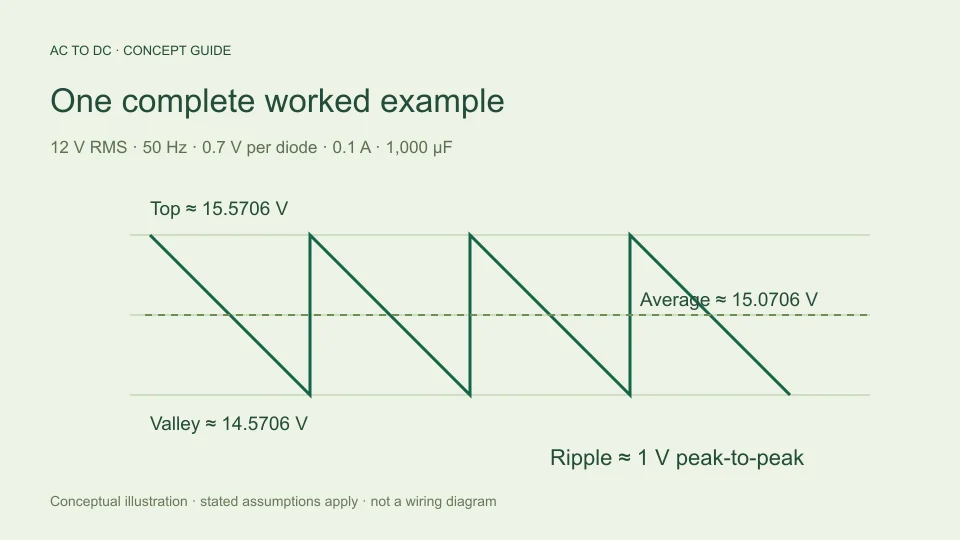
For a sinusoidal 12 V RMS input, the sine peak is about 16.9706 V. With an assumed 0.7 V per diode, the bridge top estimate is 16.9706 − 1.4 = 15.5706 V. With an assumed 0.5 V per diode, it becomes 15.9706 V.
The 0.2 V change in each assumed diode drop changes the pair loss by 0.4 V. Under the calculator’s other fixed assumptions, the available top, estimated average, and estimated valley all move by that same 0.4 V. The ripple equation itself does not include diode drop directly.
Using 50 Hz input, 0.1 A constant load, and 1,000 µF, estimated ripple is 1 V p-p in either comparison. The average estimates are therefore about 15.0706 V and 15.4706 V respectively. This is a clean sensitivity exercise because only the assumed diode drop changes. It is not evidence that changing a real component will leave all other circuit conditions unchanged.
The same drop matters more at a lower input
An assumed 1.4 V bridge-path loss occupies a larger fraction of a small available sine peak than a large one. This follows from comparing the same subtracted quantity with different starting values. It explains why a fixed-loss approximation can visibly change the result at lower modeled voltages.
For 3 V RMS, the sine peak is approximately 4.2426 V. Subtracting an assumed 1.4 V pair loss leaves about 2.8426 V at the modeled top before ripple. For 12 V RMS, the same pair loss leaves about 15.5706 V. The absolute subtraction is identical, but its relative effect differs.
Near the assumed conduction threshold, the fixed-drop model becomes especially crude. It should not be treated as a detailed description of a diode turning on abruptly at one exact voltage. The calculator’s threshold handling is a boundary rule for its simplified estimate, not a substitute for the component’s continuous current-voltage behavior.
Why ideal unfiltered modes ignore the setting
The ideal full-wave and half-wave equations are derived by integrating exact mathematical waveforms with zero diode drop. Ideal full-wave average is 2Vm/π; ideal half-wave complete-cycle average is Vm/π. Their purpose is to provide clear analytical reference values.
Subtracting a fixed loss from every point of an ideal rectified waveform would imply negative output near its zero crossings unless the waveform were also clipped. Clipping changes the conduction interval, which changes the area being averaged. A physically meaningful nonideal unfiltered model therefore needs a defined waveform and its own integration or approximation.
The calculator avoids silently combining incompatible assumptions. It hides and ignores the diode-drop, load-current, and capacitor inputs in ideal modes. If the question requires a lossy unfiltered waveform, neither the zero-drop ideal formula nor the filtered bridge estimate should be presented as an exact answer to that different problem.
Charging current is not always load current
In a capacitor-input supply, the capacitor supplies the load between charging intervals. Replenishing charge can occur during a shorter part of the AC cycle. Consequently, a diode’s instantaneous conducting current need not equal the average load current at every moment.
This matters when selecting an operating point from a forward-voltage curve. The calculator asks for a constant load-current assumption for its discharge equation, but it does not solve the charging-current waveform through the bridge. It cannot determine a self-consistent time-varying diode drop from source resistance, capacitance, and device curves.
A more detailed analysis may need source impedance, the actual diode characteristic, capacitor ESR, and the timing of conduction. Those inputs can affect one another. The fixed-drop model intentionally avoids claiming that level of detail. It gives a transparent first estimate when its simplified assumptions are useful and clearly identifies what remains outside the calculation.
Forward drop is not a complete rectifier specification
Even a carefully chosen forward-voltage assumption does not establish reverse-voltage capability, allowable average or surge current, thermal behavior, recovery characteristics, or package suitability. These are separate characteristics and should be read under their own specified conditions.
Toshiba’s explanation of diode absolute-maximum ratings distinguishes several current and voltage rating terms. A calculator’s accepted input range should never be interpreted as a component’s ratings or a safe operating instruction. Software limits and device limits answer different questions.
Likewise, a lower assumed forward drop does not automatically make one device the best choice. A useful component comparison would need the actual application requirements and relevant specifications. This educational voltage model does not make that selection and does not infer practical equipment suitability from the displayed DC average.
Report the assumption with the estimate
Record the per-diode setting, the fact that the bridge model uses two conducting drops, and the operating condition or source used to choose the setting. Keep that information with RMS input, load current, capacitance, frequency, and the resulting average, peak, valley, and ripple.
If the expected output differs from a measurement, first check whether both calculations assumed the same diode loss and whether the measurement conditions match the input definition. Then consider the omitted source and charging effects. Increasing displayed precision cannot resolve a mismatch between a fixed-drop approximation and a changing physical characteristic.
The value of this setting is transparency. A user can see the assumed loss, change it deliberately, and understand its influence on the estimate. The limitation is equally important: one fixed number cannot represent every current and temperature in a real rectifier waveform. A useful result states both the number and the model that gave it meaning.
Use a range when the assumption is uncertain
If the intended calculation only supports a plausible interval of forward-drop assumptions, compare endpoints rather than hiding uncertainty behind one precise output. For example, repeating the same filtered calculation with two explicitly chosen per-diode values produces a corresponding interval of modeled average and valley voltages. Label those endpoints as scenarios, not guaranteed device limits unless the underlying component data actually establishes such limits.
Keep the other settings fixed during this sensitivity exercise so the influence of diode drop is identifiable. Then record which omitted effects could also change the result. This approach makes uncertainty visible and helps distinguish “the calculator arithmetic is precise” from “the physical input assumption is well established.” A long output decimal cannot compensate for an unsupported component assumption.
Filed under component models rectifier basics