AC/DC Calc
rectifier basics · power supply concepts
Single-Phase vs Three-Phase Rectifiers: Voltage and Ripple
Compare bridge topology, line-to-line input voltage, six-pulse timing, capacitor charging, and the assumptions behind three-phase output estimates.
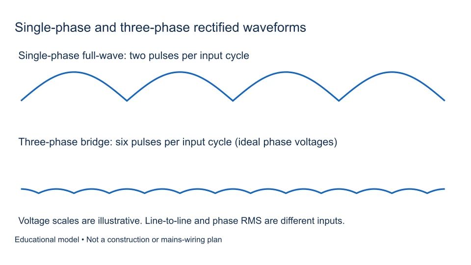
A single-phase full-wave bridge produces two rectified pulses per input cycle. A conventional three-phase full-wave diode bridge produces six. That difference changes the output waveform and filtering problem, but it does not make three-phase output automatically regulated or free of ripple.
The voltage conventions also change. A single-phase calculation usually begins with the RMS voltage across its two AC terminals. Three-phase equipment may specify either line-to-line or phase-to-neutral voltage. Confusing those quantities can introduce a factor of √3 before the rectifier calculation has even started. This guide compares the circuits conceptually; it is not an installation or mains-wiring procedure.
Define the supply before comparing the bridges
A balanced three-phase supply contains three sinusoidal phase voltages separated by 120 electrical degrees. In a balanced wye system, line-to-line RMS voltage is √3 times phase-to-neutral RMS voltage. Those are two measurements of the same supply, not alternative names for one number.
Write the quantity beside every input: for example, “24 V RMS line-to-line.” Do not assume that a transformer nameplate, a phase measurement, and a drive’s input rating describe the same terminals. Our RMS, peak, and average guide explains the measurement conventions that still apply to each waveform.
Compare specific topologies, not broad labels
| Configuration | Typical diode count | Rectified pulse repetition | Essential distinction |
|---|---|---|---|
| Single-phase half-wave | One | f | Only one input half-cycle contributes |
| Single-phase full-wave bridge | Four | 2f | Two diodes conduct in each current path |
| Three-phase full-wave bridge | Six | 6f | Output follows successive line-to-line segments |
A center-tapped single-phase full-wave circuit is another topology; its transformer convention differs from a four-diode bridge. Likewise, “three-phase rectifier” can describe arrangements other than the six-diode circuit discussed here. Identify the actual topology before choosing a formula. The half-wave/full-wave comparison covers the single-phase distinction in more detail.
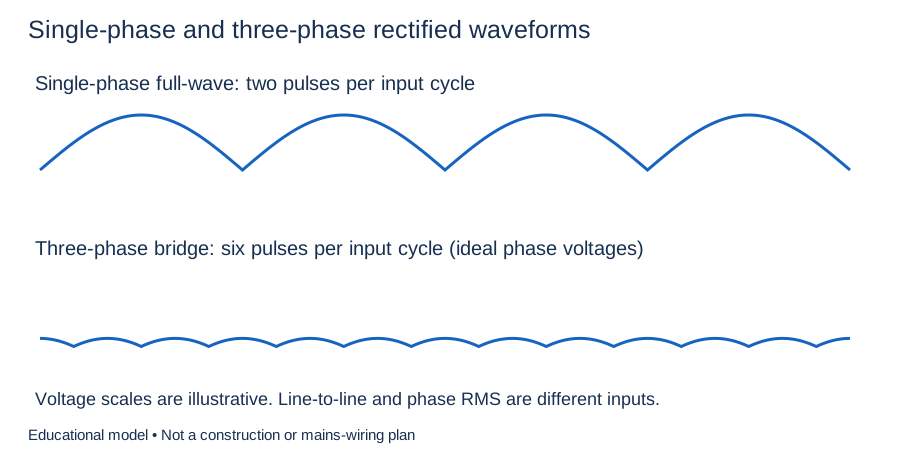
The pulse comparison describes rectification. A downstream filter or regulator changes the delivered waveform and cannot be inferred from diode count alone.
How the six-diode bridge selects a voltage
For the ideal balanced bridge, the conducting upper diode connects the most positive phase to the positive DC terminal. The conducting lower diode connects the most negative phase to the negative terminal. The load therefore sees the difference between those phases: one of the instantaneous line-to-line voltages.
The selected pair changes every 60 electrical degrees. These six successive intervals explain the term six-pulse. It does not mean the input has six phases. In the ideal description, two diodes carry load current at a time. Real source inductance makes current transfer take a finite interval; the Virginia Tech rectifier-model thesis illustrates this commutation overlap and why ideal switching is an approximation.
Ripple timing: 2f versus 6f
At 50 Hz, a single-phase full-wave bridge repeats its rectified output at 100 Hz, while a balanced six-pulse bridge repeats at 300 Hz. At 60 Hz the corresponding frequencies are 120 Hz and 360 Hz. The intervals between pulse peaks are about 10 ms and 3.33 ms in the 50 Hz examples.
More frequent charging opportunities can reduce the storage interval a filter must bridge. However, ripple magnitude also depends on capacitance, current, conduction interval, source impedance, and balance. A frequency advantage is not a universal “three times less ripple” guarantee. See rectifier ripple frequency for the difference between pulse repetition and voltage variation.
Derive the ideal average using line-to-line RMS
For the conventional ideal six-pulse model with balanced sinusoidal input, negligible source inductance, no diode drop, and continuous conduction, the average is:
Vdc = (3√2/π) × VLL,RMS ≈ 1.35047 × VLL,RMS.
One way to see the factor is to average six identical 60° segments. Each segment is a line-to-line cosine centered on its crest. Integrating its crest magnitude √2 VLL,RMS over −π/6 to +π/6 and multiplying by 3/π gives the expression above. MathWorks’ official average-value rectifier documentation explicitly uses line-to-line RMS and this conversion ratio.
For an illustrative 24 V RMS line-to-line source, that average is approximately 32.411 V. Its line-to-line sine crest is √2 × 24 ≈ 33.941 V. The mean and crest are different quantities even though both describe the same ideal source.
A capacitor-input bus is not the same average model
A reservoir capacitor can charge toward the available line-to-line crest and discharge between charging intervals. At very light load its bus voltage can therefore approach the crest, less conducting-path losses, rather than the 1.35047 average. Loaded operation requires the actual charging and discharge behavior.
For a conceptual 400 V line-to-line input, 1.35047 times the input is about 540.2 V, whereas its sinusoidal crest is about 565.7 V. These figures demonstrate model selection; they are not safe component ratings or a construction example. Do not insert 400 V into the site’s single-phase filtered-bridge model to estimate an industrial DC bus. The capacitor calculation guide explains its narrower charge-balance assumptions.
Diode losses, harmonics, and equipment stress
Two conducting devices still produce losses in the three-phase bridge. Forward voltage depends on current and temperature, so a fixed-drop estimate cannot establish heat-sink size or junction temperature. The bridge diode-loss article separates a voltage-drop approximation from thermal design.
DC ripple and AC input-current distortion are also different problems. A relatively smooth DC bus does not prove sinusoidal mains current. ABB’s harmonics guide discusses six-pulse drive front ends, inductance, and multi-pulse alternatives. Harmonic compliance requires a system assessment; the output-voltage multiplier cannot predict it.
Keep the voltage comparison separate from power
Neither the 0.9003 single-phase average factor nor the 1.35047 three-phase factor is an efficiency. Both relate particular voltage quantities under different circuit assumptions. Efficiency instead compares real output power with real input power at the same operating point. RMS input current alone is insufficient unless the input waveform and power factor are also accounted for. Likewise, multiplying an average DC voltage by an arbitrary current limit does not establish transformer capacity. A useful comparison records source ratings, load demand, thermal limits, and input-current behavior separately from the average-voltage result. Otherwise a correct voltage calculation can support an incorrect equipment conclusion.
Controlled rectifiers and industrial applications
Replacing diodes with controlled devices such as silicon-controlled rectifiers adds firing control. The average output then depends on firing timing and load/conduction assumptions. A diode-bridge result cannot simply be relabeled as an SCR result.
Industrial drives may rectify three-phase AC into a DC link and then use an inverter stage to supply a motor. Other equipment uses active front ends or additional DC-DC conversion. Consequently, finding a rectifier inside a product does not mean its final output is unregulated DC. This site’s calculator intentionally does not calculate SCR firing behavior, drive performance, commutation overlap, or three-phase equipment ratings.
Frequently asked questions
Does a three-phase bridge need a neutral?
The conventional six-diode bridge uses three line terminals and develops its output from line-to-line differences. That observation does not specify protective earthing, isolation, protection, or the correct connection of any particular product. Follow its documented supply requirements.
Can a larger capacitor replace three-phase input?
No. Capacitance stores charge; it does not create extra supply phases or change a two-pulse topology into six-pulse rectification. It can also increase charging-current stress. Hammond’s rectifier guide distinguishes filter configurations and their current implications.
Which calculator should I use here?
Use the AC to DC calculator only for its stated single-phase models. For three-phase design, use a suitable circuit model with verified source and load conditions. Start any comparison by recording topology, input measurement convention, filtering, and the output quantity required. Those four decisions matter more than memorizing a multiplier.
Filed under rectifier basics power supply concepts