AC/DC Calc
voltage measurement · rectifier basics
RMS, Peak, and Average Voltage: Keep the Measurement Convention
Distinguish sine-wave RMS, peak, signed average, rectified average, and filtered estimates before calculating AC to DC output.
A voltage number becomes meaningful when its measurement convention is attached. “12 volts” could describe a steady DC level, a sinusoidal RMS reading, a positive peak, or a peak-to-peak span. These values describe different features of a waveform. Treating them as interchangeable can produce a large calculation error even when every arithmetic step is correct.
The AC to DC calculator asks for sinusoidal AC RMS voltage at the rectifier input. Its formulas depend on that definition. This guide derives the main relationships, shows what changes after rectification, and explains why a filtered average must be interpreted separately. The purpose is to make the input and output quantities clear before using a multiplier.
Peak is the waveform’s largest excursion
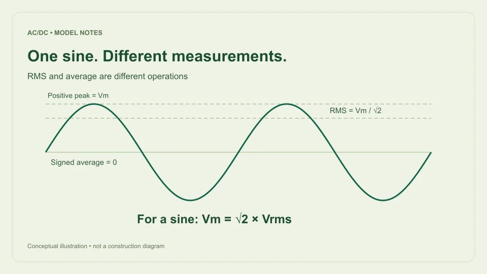
For a symmetric sine written as v = Vm sin θ, Vm is the positive peak relative to the waveform’s zero reference. The negative peak is −Vm. Peak-to-peak voltage is the span from the negative extreme to the positive extreme, so Vpp = 2Vm for this waveform.
The distinction is easy to lose when a display uses abbreviations. A value labeled Vpk is not the same as a value labeled Vpp. If the positive peak is 10 V, the symmetric sine extends to −10 V and spans 20 V peak-to-peak. Entering 20 V as the peak would double every result derived from it.
The reference point also matters. A DC offset shifts the waveform vertically. Its highest instantaneous voltage relative to ground then includes the offset, while the sine’s AC amplitude does not. This site’s calculator assumes a sinusoidal AC input without an added DC offset; it does not infer waveform components from an unexplained voltage label.
RMS comes from the mean square
Root mean square means exactly what its name describes: square the instantaneous values, find their mean over the chosen interval, and take the square root. For a periodic waveform, the usual complete-cycle RMS is the square root of the integral of v² divided by the cycle length.
For a sine, v² = Vm² sin² θ. The mean of sin² θ over a complete cycle is one half, so Vrms = Vm/√2. Reversing that expression gives Vm = √2 Vrms. The familiar factors of approximately 0.707107 and 1.414214 are consequences of the sine waveform, not general voltage conversion constants.
As a manufacturer measurement reference, Keysight’s guide to better AC RMS measurements discusses the importance of identifying what an AC meter reports and how waveform shape affects interpretation. The analytical sine relationship here is derived from the mean-square definition rather than assumed for every signal.
Signed average can be zero while RMS is positive
The signed average of a symmetric sine is zero over a complete cycle because its positive and negative areas cancel. Its RMS remains positive because squaring removes the sign before averaging. There is no contradiction: these operations answer different questions.
Consider a sine with a 10 V peak. Its complete-cycle signed average is 0 V, its RMS is about 7.0711 V, and its peak-to-peak span is 20 V. Describing all three prevents a reader from confusing “zero average” with “zero waveform.” A zero signed mean does not imply that the signal carries no varying voltage.
The averaging interval must also be stated. Averaging only a positive half-cycle produces a different number from averaging the original signed sine over the entire cycle. A calculator result can be mathematically correct for one interval and inappropriate for a question that assumes another. Always keep the interval and waveform together when reporting an average.
Rectification changes the average without changing the ideal crest
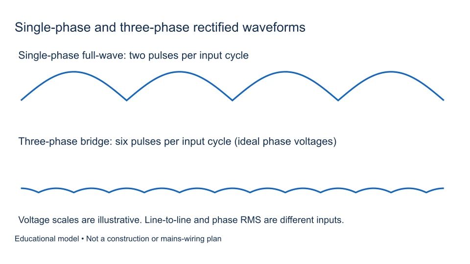
An ideal full-wave rectifier reflects each negative half-cycle upward. The resulting waveform is Vm|sin θ|. Its average over a complete input cycle is 2Vm/π, approximately 0.636620 Vm. Its positive crest remains Vm, and its valley is zero.
An ideal half-wave rectifier passes one half-cycle and blocks the other. Averaged over the whole input cycle, including the zero-output half, its mean is Vm/π, approximately 0.318310 Vm. That is half the full-wave mean because half the contributing area is absent.
Neither rectified average should be substituted for RMS. In the ideal full-wave case, squaring the reflected waveform gives the same squared values as the original sine, so its RMS is unchanged. In the ideal half-wave case, the squared contribution occupies only half as much of the complete cycle. From that integration, its output RMS is Vm/2. These comparisons concern ideal waveforms without filtering or diode loss.
Work through one 12 V RMS input
Start with a sinusoidal input of 12 V RMS. Its positive peak is 12√2, approximately 16.9706 V. Its negative peak is approximately −16.9706 V, and its input peak-to-peak span is approximately 33.9411 V. The signed average of the original sine is zero.
After ideal full-wave rectification, the complete-cycle average is 2 × 16.9706/π, approximately 10.8038 V. The ideal output RMS remains 12 V, the peak remains 16.9706 V, and the valley is zero. After ideal half-wave rectification, the complete-cycle average is approximately 5.4019 V and output RMS is approximately 8.4853 V.
Those values do not compete to be the one “correct voltage.” They describe different properties. A clear result might say “10.8038 V ideal full-wave average from 12 V RMS sinusoidal input” rather than merely “10.8 V DC.” The longer label makes it much harder to confuse the pulsating average with a smooth regulated supply.
Filtering introduces a new waveform
A capacitor-filtered bridge no longer follows the entire rectified sine between crests. The capacitor stores charge near the top and supplies the load while the input falls below it. Its voltage therefore depends on load current, capacitance, frequency, source behavior, and diode characteristics.
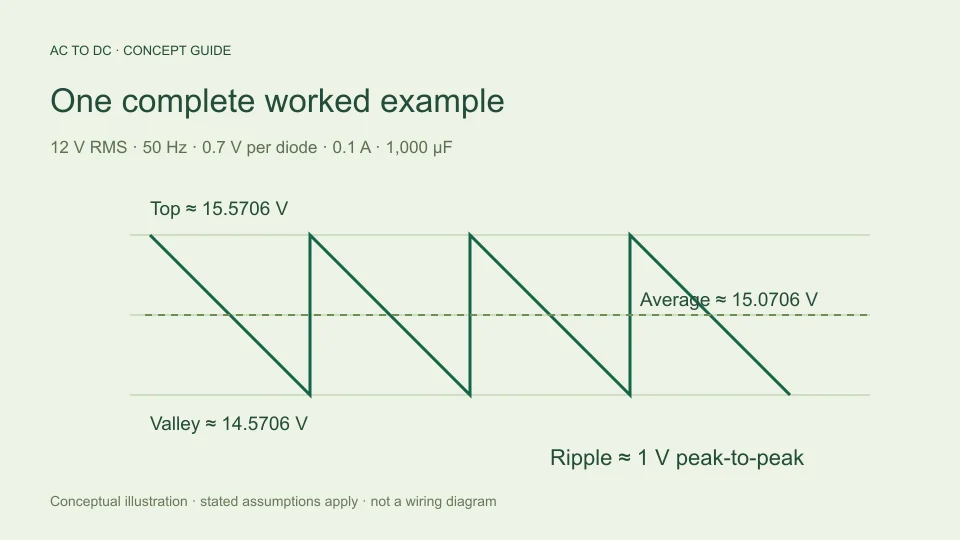
This site’s simplified filtered model estimates top voltage as √2 Vrms minus two fixed diode drops. It estimates peak-to-peak ripple from I/(2fC), then takes the midpoint of an approximately linear discharge as average DC. The capacitor ripple guide works through that approximation in detail.
The filtered average should not be substituted for the unfiltered full-wave mean. Nor should it be called the same as RMS without calculating the waveform’s mean square. A small-ripple waveform may have numerically similar average and RMS values, but closeness in a particular case does not make the definitions interchangeable. State the quantity the model actually calculates.
Why the waveform assumption matters
Two waveforms can have the same RMS value and different peaks. The sine’s peak-to-RMS ratio is √2, but a symmetric square wave with levels +A and −A has RMS A and peak A. A short-duration pulse waveform can have a much larger peak for the same RMS value, depending on its timing.
Consequently, a true RMS reading alone does not identify the peak of an arbitrary waveform. The calculator’s sine relationship is justified because the selected model explicitly specifies a sine. If the source is clipped, heavily distorted, pulse-width modulated, or otherwise nonsinusoidal, the input needs a different mathematical description.
This is also why changing from a meter reading to an oscilloscope label requires care. Before comparing numbers, identify the quantity and interval used by each instrument setting. Consult the instrument’s own documentation for its measurement mode, bandwidth, and permitted signal conditions. The calculator does not evaluate those instrument limitations or recover a waveform from a single displayed number.
A practical reading checklist
Before entering a value, identify where the voltage is measured, whether it is RMS or peak, whether the source is reasonably described as sinusoidal, and which rectifier model will be used. If the number comes from a label rather than a measurement, keep its stated operating condition attached.
After calculation, report the selected output quantity. For ideal unfiltered models, the average is a complete-cycle waveform mean with zero valleys. For filtered mode, the average and valley are approximate values under the selected load and capacitor assumptions. Displayed digits are numerical formatting, not a claim that a physical measurement has that many meaningful digits.
When two results disagree, compare their definitions before comparing their arithmetic. A peak-to-peak reading, a full-wave average, and an RMS reading can all describe the same waveform with different numbers. Once the convention is explicit, the correct formula becomes much easier to choose and the result becomes easier to reproduce.
Distinguish conversion precision from measurement precision
The factors √2 and π can be evaluated to many decimal places, but that does not add information to an input measurement. If the source is recorded as 12 V RMS without an uncertainty statement, displaying 16.970562748 V as a computed peak does not establish that the physical peak is known to the nearest nanovolt.
Keep extra digits while checking arithmetic, then report a suitable number of meaningful digits for the original measurement and purpose. A calculator can format a result consistently, but it cannot infer an instrument’s calibration, bandwidth, resolution, or uncertainty from a numerical input alone. Those properties belong to the measurement process.
A unit change is another useful illustration. Writing 0.012 kV instead of 12 V changes the scale, not the waveform convention. Either number can still be RMS, peak, or an average depending on its label. Converting volts to millivolts likewise does not turn an RMS quantity into a peak quantity. First identify the measurement definition; then handle units and numerical precision as separate steps.
For recorded results, a short note such as “sinusoidal input, 12 V RMS; calculated peak approximately 16.97 V” communicates more than a long unqualified decimal. It preserves the assumption that makes the relationship valid and avoids presenting calculation precision as measurement certainty.
Filed under voltage measurement rectifier basics