AC/DC Calc
power supply concepts
Linear vs Switching AC to DC Power Supplies: Compare the Whole System
Compare conventional linear and switching supplies by conversion stages, regulation, heat, ripple, efficiency, and the needs of the actual load.
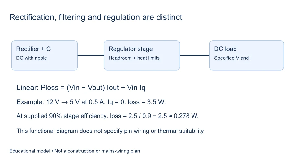
A linear supply and a switching supply can both deliver regulated DC, but they control energy differently. A conventional linear AC-to-DC supply usually combines a line-frequency transformer, rectifier, reservoir capacitor, and linear regulator. An isolated switching supply commonly rectifies the incoming AC before transferring energy through a controlled high-frequency conversion stage.
The useful question is not which label is universally better. It is which complete supply meets the required voltage, load behavior, noise limits, thermal conditions, size, isolation, and cost constraints. Comparing a linear-regulator efficiency calculation with an unrelated AC-to-DC supply rating confuses two different measurement boundaries.
Distinguish the regulator from the complete power supply
A linear regulator is a DC-to-DC control stage. It can follow a transformer supply, a battery, or a switching converter. Similarly, a switching regulator can be one stage inside a larger AC-to-DC system. The names do not automatically describe the source, isolation, or all preceding losses.
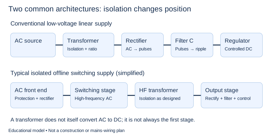
Compare complete input-to-output paths before comparing the losses of one regulator within them.
ROHM’s transformer-system overview places the low-frequency transformer before rectification. Its switching-system overview describes the alternative arrangement in which rectification precedes high-frequency switching. These are representative architectures, not an exhaustive list of power-supply circuits.
How linear regulation uses voltage headroom
A linear regulator adjusts a pass element to maintain its output within the specified operating conditions. It requires sufficient input-to-output headroom, known as dropout voltage. Dropout depends on the device and operating point; it is not always a fixed two-volt allowance.
Check the lowest input voltage, including ripple valleys and relevant supply variation, against the desired output plus required headroom. An acceptable average input does not guarantee regulation throughout a ripple cycle. The unregulated versus regulated supply guide explains why smoothing and regulation remain different functions.
The regulator must also stay within its input range, output-current limits, stability requirements, and thermal limits. Dropout is one necessary check, not an assessment of the entire design. Texas Instruments’ SLVA118 application report discusses the relationship between these LDO operating considerations.
Calculate linear-stage loss explicitly
For a simple single-input positive linear regulator, let Vin be the regulator input voltage, Vout its output voltage, Iout the load current, and Iq its ground or quiescent current. Under the assumption that input current is Iout + Iq:
- Output power: Pout = Vout × Iout.
- Input power: Pin = Vin × (Iout + Iq).
- Regulator loss: Ploss = (Vin − Vout) × Iout + Vin × Iq.
- Stage efficiency: η = Pout/Pin.
If Iq is negligible compared with Iout, efficiency approaches Vout/Vin and loss approaches (Vin − Vout) × Iout. These simplified limits should not hide an appreciable quiescent-current contribution at light load. Devices with separate bias rails or different current paths need their actual input-power relationships.
Texas Instruments’ TPS7A11 datasheet is an example where a separate bias supply must be included in an efficiency calculation. It illustrates why the simple single-rail expression is not universal.
Work through a 12 V to 5 V example
Assume a hypothetical linear stage has a steady 12 V input, 5 V output, 0.2 A load, and 1 mA quiescent current. Its output power is 1 W. Input power is 12 × 0.201 = 2.412 W. Calculated regulator loss is therefore 1.412 W and stage efficiency is approximately 41.46%.
Neglecting quiescent current would give a 1.4 W loss and 41.67% efficiency. The approximation is close for this assumed load, but the omitted term becomes more important as load current falls. At 1 mA load and the same hypothetical 1 mA quiescent current, output power is 0.005 W while input power is 0.024 W: efficiency is only about 20.83%.
These are arithmetic examples, not measurements or specifications of a particular regulator. They exclude rectifier, transformer, wiring, and other system losses. They also do not establish whether a package or circuit board can dissipate the calculated heat.
Heat requires a separate thermal check
Electrical loss becomes heat that must leave the device through its package and surroundings. A rough steady-state estimate may use junction temperature rise ≈ Ploss × θJA, but the thermal resistance must apply to the actual package, board, airflow, and test conditions. A favorable number from a different layout is not a guaranteed result.
The TPS735-Q1 datasheet explains the voltage-drop and load-current contribution to dissipation and the significance of board heat transfer. Its particular ratings are not transferable to an unspecified regulator.
Reducing excess input voltage can reduce linear-stage heating, provided dropout margin remains adequate at the minimum input. A heatsink may address a thermal constraint; it does not recover the energy already dissipated or correct an incompatible input rating.
Switching regulation changes the loss balance
A switching regulator controls energy transfer using switching devices and storage elements. Its losses can include switch conduction, switching transitions, magnetic losses, rectification, controller consumption, and capacitor-related losses. The proportions change with load, input voltage, switching frequency, topology, and component selection.
An ideal buck converter in continuous conduction has the familiar steady-state relationship Vout ≈ D × Vin, where D is the switch duty ratio. A duty ratio of 5/12 is about 41.67%, but that number is not the converter’s efficiency. Duty ratio describes timing; efficiency compares useful output power with total input power.
ROHM’s step-down operating-principle explanation describes the switched input, energy-storage elements, and feedback involved in buck conversion. An isolated offline flyback uses a different relationship; the buck expression must not be applied to every switching AC-to-DC supply.
Compare total efficiency at the same boundary
For a complete AC-to-DC supply, efficiency is average DC output power divided by real AC input power at the stated conditions. AC RMS voltage multiplied by RMS current gives apparent power in volt-amperes; it is not automatically real input watts. Power factor and the input-current waveform matter.
If a hypothetical supply delivers 24 W and measured real input power is 30 W, its efficiency is 80% and the difference is 6 W. That result belongs to the tested input, load, and temperature conditions. It cannot be inferred from a duty ratio, a diode drop, or the output-voltage label alone.
Our AC-to-DC calculator solves defined voltage and regulator models. Treat a regulator-stage estimate as a stage estimate and use measured or suitably specified real input power when evaluating overall conversion efficiency.
Noise and regulation are not one-number comparisons
| Requirement | Useful question |
|---|---|
| Low output noise | What frequency range and measurement bandwidth apply? |
| Load transients | How much deviation occurs when load current changes? |
| Line ripple rejection | Does the input variation occur within the regulator’s useful rejection range? |
| Thermal performance | What loss and temperature rise occur in the intended installation? |
| Size and mass | Which transformer, filter, shielding, and cooling requirements apply? |
Switching introduces periodic transitions that require attention to filtering and electromagnetic compatibility. Linear regulation can be useful for noise-sensitive rails, but rejection varies with frequency and operating conditions. A switching preregulator followed by an LDO can be a deliberate combination rather than a contradiction. Texas Instruments’ low-IQ regulator training discusses complementary regulator use.
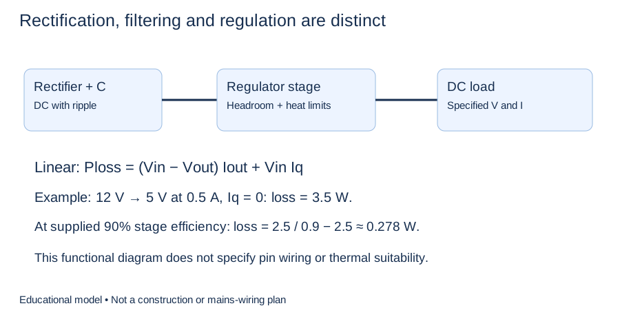
Check headroom and thermal conditions before assuming a regulator will hold the requested output.
Questions that help make the comparison useful
Is a switching supply always more efficient?
No universal statement covers every operating point. Compare actual loss or measured efficiency at the relevant load and input conditions, especially light load and standby operation.
Does a linear supply have no ripple?
No. Input ripple, finite rejection, noise, and load response remain relevant. Read the specified conditions and distinguish them from an ideal flat output.
Which should I choose?
Write the load requirements first, then compare complete supplies against them. The power-supply selection guide provides that checklist. Keep system boundaries clear, calculate heat honestly, and require evidence for claims about performance.
Filed under power supply concepts