AC/DC Calc
power supply concepts
AC to DC Power Supply Stages: From Input to Regulated Output
Follow the signal through a conventional transformer supply and an isolated switching supply, and see why rectification alone is not regulation.
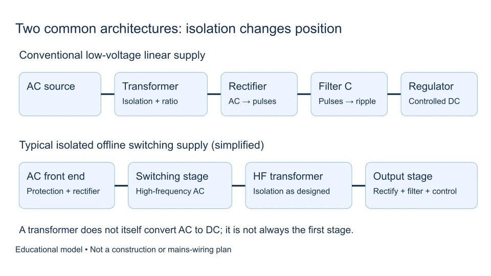
An AC-to-DC power supply changes an alternating input into an output suitable for a particular DC load. Rectification gives the current a preferred direction, but the complete supply may also need isolation, filtering, regulation, protection, and control. These functions answer different questions: which direction does current flow, how much does voltage vary, and what keeps the output within its specified limits?
There is no single component order that describes every supply. A conventional low-frequency transformer supply reduces and isolates AC before rectification. An isolated offline switching supply generally rectifies the incoming AC first, then transfers switched energy through a high-frequency transformer. Understanding that difference prevents a block diagram from becoming a misleading construction recipe.
Read the diagram as a signal path
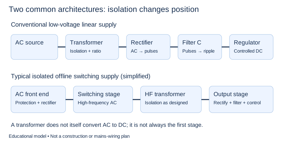
The isolation transformer appears before low-voltage rectification in the conventional path and within the switching conversion stage in the isolated offline path.
A useful block diagram identifies what enters and leaves each stage. A sine wave entering a diode bridge becomes a rectified waveform. A reservoir capacitor changes that waveform into a varying DC level. A regulator controls a later output within its operating conditions. Protection functions act alongside this signal path; they are not evidence that an exposed circuit is safe to touch.
For a more focused description of the diode stage, see the full-wave bridge rectifier guide. The distinction between a waveform average and a smoothed level is explained in RMS, peak, and average voltage.
Stage 1: establish the input conditions
The input specification includes voltage range, frequency, phase configuration, and the environment in which the supply operates. A nominal AC voltage is normally an RMS value. It does not describe the instantaneous crest, and a nominal value is not a guarantee that the input never changes.
For a sine wave, peak voltage is the RMS value multiplied by the square root of two. That relationship describes the waveform, not the desired DC output. A regulated 12 V supply can accept a much higher AC input because additional conversion stages intervene. Conversely, a transformer secondary marked 12 V AC does not automatically become regulated 12 V DC after a bridge.
Use the voltage at the actual rectifier input when making a rectifier calculation. A mains label, transformer primary rating, and loaded secondary measurement are different quantities.
Stage 2A: the conventional transformer path
In the conventional arrangement, a transformer operating at the line frequency provides the required voltage relationship and, when it has appropriately separated windings and construction, galvanic isolation. Its secondary then feeds a rectifier. ROHM’s transformer-system explanation describes this sequence and the subsequent need for rectification and stabilization.
The ideal turns relationship is Vs/Vp = Ns/Np. Real winding resistance, regulation, losses, and loading affect the secondary voltage. A turns ratio therefore supplies a starting relationship rather than a complete prediction of the loaded DC rail.
Isolation must be established by the actual construction, ratings, installation, and applicable requirements. A symbol showing two windings is not a safety assessment. An autotransformer, for example, must not be treated as though it necessarily provides separated primary and secondary circuits.
Stage 2B: the isolated switching path
An offline switching supply commonly rectifies and smooths the incoming AC on its primary side. A controlled switching device then applies high-frequency pulses to a magnetic component. In an isolated flyback implementation, energy is transferred through coupled windings and rectified on the secondary side before output filtering. ROHM’s isolated flyback overview explains this different order of conversion.
The switching frequency is distinct from the incoming 50 Hz or 60 Hz line frequency. The output behavior depends on topology, control, load, and components; it cannot be obtained by applying a low-frequency bridge-and-capacitor approximation to every internal waveform.
Some supplies include power-factor-correction stages, synchronous rectification, or additional DC-to-DC outputs. Others are not isolated. The label “switching” alone establishes neither isolation nor a particular output quality.
Stage 3: rectification changes direction, not flatness
A half-wave diode stage passes one input polarity and blocks the other. A full-wave arrangement uses both halves of the input cycle. A standard bridge has four diodes, with two conducting in each active current path. Its load polarity remains the same while the active diode pair changes.
Without an energy-storage filter, the resulting voltage is still strongly time dependent. “DC output” can refer to its nonzero average rather than a flat trace. This is why half-wave and full-wave comparisons must state which output quantity is being compared.
Diodes have current- and temperature-dependent forward behavior. A fixed forward drop is a modeling assumption, not a universal component property. Hammond Manufacturing’s rectifier guide separates rectifier and filter arrangements, illustrating why their voltage and current relationships are not interchangeable.
Stage 4: smoothing stores energy between charging intervals
A reservoir capacitor charges when the available rectified voltage exceeds its terminal voltage sufficiently to supply current through the conducting path. Between charging intervals, it supplies the load and its voltage declines. More capacitance generally reduces this decline under otherwise comparable conditions, but source impedance and charging behavior still matter.
For a simplified full-wave bridge with constant load current, small ripple, and instantaneous recharging, ripple is approximately I/(2fC). Texas Instruments’ TIDUB95 reference design, section 3.1 explains the relationship between charge, capacitance, and the twice-line-frequency charging pattern.
That approximation does not calculate capacitor ripple-current rating, equivalent series resistance losses, inrush current, or transformer heating. Filtering must be evaluated for more than its capacitance value. The capacitor ESR and ripple-current guide explains these separate limits.
Stage 5: regulation needs operating headroom
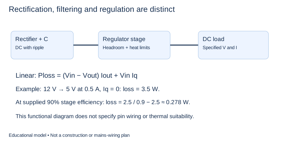
The regulator must remain within its operating range during the input valley, not just at the average voltage.
A linear regulator controls a series pass element. Its input must remain high enough for the desired output plus the device’s required dropout headroom. A switching regulator transfers energy through controlled switching and storage elements. Neither can ignore input limits, available power, transient response, stability requirements, or temperature.
Texas Instruments’ linear-regulator application report SLVA118 discusses dropout, quiescent current, efficiency, and thermal constraints. These are device-level operating considerations, separate from the earlier rectifier waveform average.
A calculation across the conventional stages
Take a modeled 12 V RMS secondary, a bridge with an assumed 0.7 V drop per conducting diode, 50 Hz input, a constant 0.1 A load, and 1,000 µF. The sine crest is about 16.97 V. Subtracting two assumed diode drops gives a 15.57 V available top. Estimated ripple is 0.1/(100 × 0.001) = 1 V peak-to-peak.
The approximate average is therefore 15.07 V and the valley is 14.57 V. Those are unregulated estimates. A proposed 12 V linear output would have about 2.57 V of modeled valley headroom, before allowing for input variation and other omitted effects. Its approximate pass-element dissipation at the average input would be (15.07 − 12) × 0.1 ≈ 0.307 W, excluding quiescent-current loss.
This arithmetic tests stated assumptions; it does not validate a transformer, regulator, heatsink, enclosure, or mains installation. Check the limits of the simple calculator before interpreting it as a real supply specification.
Questions about the complete conversion path
Does a bridge rectifier provide isolation?
No. Diodes establish a preferred current direction. Isolation requires an appropriate isolation barrier and its supporting construction. A bridge connected to a hazardous source does not make its output safe.
Does a larger capacitor guarantee regulated DC?
No. A capacitor reduces particular voltage variations under defined loading conditions. It does not enforce an exact output setpoint as the input or load changes.
Which stage determines the final output?
The output specification belongs to the complete supply operating within its ratings. Follow the signal through each stage, keep its assumptions attached, and distinguish a useful educational estimate from verified equipment performance.
Filed under power supply concepts