AC/DC Calc
rectifier basics
Why AC voltage alone cannot tell you the available DC current
Separate output voltage estimates from load current, transformer capacity, power, and component stress.
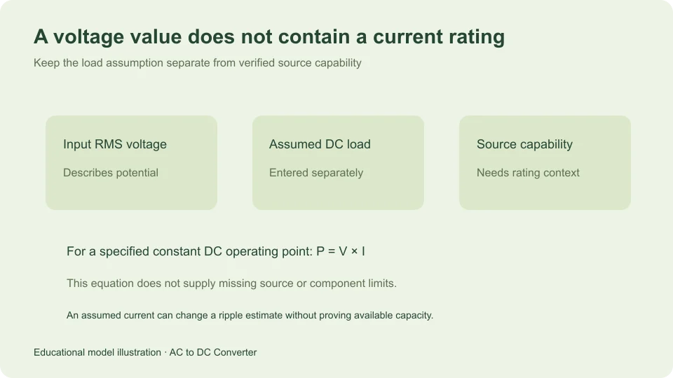
Knowing that a source provides a stated AC voltage does not tell you how much DC current can be drawn after rectification. Voltage describes a potential difference. Current depends on the connected circuit and its operating condition, while available current capacity depends on source and component constraints that a voltage value does not contain.
This distinction is easy to overlook when a calculator accepts an AC input and displays a DC voltage. The result may be useful for its defined model, but it cannot manufacture missing transformer ratings, thermal information, load behavior, or component limits. A separate current input is an assumption about the load, not a prediction that the source can support it.
Distinguish an operating current from a current rating
Operating current is the current that flows under a specified condition. A current rating describes a permitted or specified capability under stated conditions. Neither follows automatically from a nominal voltage label. Two hypothetical sources can have the same voltage and very different capacity.
For a deliberately simple resistive load at a constant DC voltage, Ohm’s law gives I = V/R. A 10 V level across 100 Ω would imply 0.1 A, while the same level across 1,000 Ω would imply 0.01 A. The resistance supplies the information that voltage alone lacks.
Even in that ideal example, calculating a demanded current does not demonstrate that a particular source can maintain the assumed voltage while supplying it. A complete operating point requires both a load description and a source description. Treating the load calculation as a source rating reverses the meaning of the result.
Understand the calculator’s current field
The capacitor-filtered bridge model asks for a DC load current in amperes. It treats that current as approximately constant during the capacitor discharge interval. The value determines how quickly charge is removed from the smoothing capacitor in the simplified calculation.
With capacitance C and discharge time Δt, the removed charge is IΔt. Since charge change equals CΔV, the estimated voltage drop is IΔt/C. For a full-wave bridge, taking the interval as approximately 1/(2f) gives ripple ΔVpp ≈ I/(2fC).
This use of current is causal within the model: you assume a load, then estimate its effect on ripple. It does not work in reverse as evidence of supply capability. Entering 0.5 A means “evaluate this assumed constant load,” not “this source is able to deliver 0.5 A safely or continuously.”
Work through two load assumptions
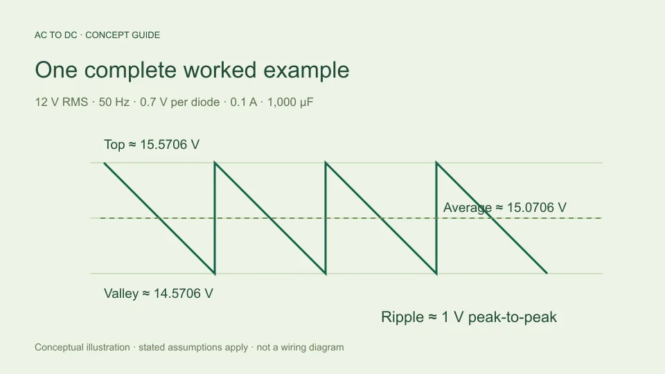
Start with the site’s illustrative 12 V RMS sine, 50 Hz frequency, 0.7 V assumed per conducting diode, and 1,000 µF capacitor. The available top under the fixed-drop model is 12√2 − 1.4, approximately 15.5706 V.
At 0.1 A constant load, estimated ripple is 1 V peak-to-peak. The midpoint average is approximately 15.0706 V, and the valley is approximately 14.5706 V. At 0.2 A, the same charge-balance formula predicts 2 V ripple, approximately 14.5706 V average, and approximately 13.5706 V valley.
Those results compare assumed loads in a simplified model. They do not establish that either current is available from an unidentified transformer or bridge. In real hardware the source and diode drops may change with current as well; the model deliberately holds those effects outside its inputs.
Power adds another quantity, not missing ratings
For a constant DC voltage and current, output power is P = VI. Multiplying an illustrative 15 V by 0.1 A gives 1.5 W. The equation connects specified operating quantities; it does not indicate where that power can come from or how much additional power is dissipated elsewhere.
If voltage or current varies with time, average power is the average of the instantaneous product v(t)i(t). Multiplying separately averaged values is not generally equivalent. The waveform and its relationship to the load matter.
This is particularly relevant when discussing a rectifier and smoothing capacitor. The source-side charging current need not be a smooth copy of the assumed DC load current. A calculation based on average output quantities should not be relabeled as a complete assessment of winding heating, diode stress, input power factor, or efficiency.
Source ratings need their own context
A transformer description may include voltage, current, or apparent-power information, but the intended rectifier and filter affect how those specifications relate to DC loading. The missing information is not hidden inside the AC voltage number; it belongs to the source and circuit documentation.
Hammond Manufacturing’s rectifier guide explicitly distinguishes transformer AC current ratings from DC load current and changes the relationship with rectifier and filter arrangement. Its guide is a reminder to use the appropriate configuration, rather than assume one current multiplier fits every supply.
The site’s voltage calculator does not implement a transformer rating selection model. It therefore does not output an allowable load current or a minimum transformer capacity. Supplying such a number without the required inputs and conditions would make the interface appear more complete while making the engineering question less defined.
Component stress is not one average number
Current can be described by its average, RMS, peak, and time-dependent pattern. Different constraints may depend on different descriptions. A current with narrow charging pulses can have an average that looks modest while its peak and RMS behavior remain important to the components carrying it.
Likewise, capacitor current and load current are not interchangeable at every instant. During part of a cycle the capacitor supplies the load; during recharge, the source also restores charge. A complete account of those paths requires a circuit model beyond the simple average discharge estimate.
The calculator’s decision to omit those stresses is intentional scope, rather than a declaration that they can be ignored. Its displayed average DC voltage answers a narrower question. Use a model that actually accepts component characteristics and source conditions when the question concerns component suitability or permitted loading.
A regulator changes the relationship again
A regulated supply adds a conversion or control stage after, or as part of, its rectification. Its input current, output current, dissipation, and output behavior depend on that stage’s design and operating range. A bridge-only voltage estimate does not describe the complete supply.
For an ideal lossless conversion stage, equal input and output power would provide one constraint, but voltage alone would still not determine current. You would also need a power demand or another current value. Real stages introduce additional operating limits and losses, so the ideal constraint is only a starting relationship.
Do not use a rectifier calculator to infer the current label of a regulated adapter from its input voltage. That label describes a product’s specified output capability under its own conditions. The calculator has no information about the product’s transformer, switching stage, regulation, thermal design, or protection behavior.
Use a set of required questions
When someone asks “How many DC amps will this AC voltage give?”, separate the question into parts. What is the source’s specified capacity? What rectifier and filter are involved? What load behavior is assumed? What output voltage quantity matters? What operating conditions and component constraints apply?
Not every problem requires the same level of analysis, but omitting those questions does not make the missing information unnecessary. If the aim is merely to understand how an assumed load affects a small-ripple voltage estimate, the main calculator provides a defined model. If the aim is to select or qualify hardware, a different and more complete assessment is needed.
Keeping those purposes separate also improves communication. “Estimated average at an assumed 0.1 A load” is a reproducible statement. “Produces 0.1 A” could incorrectly imply that the current was predicted, measured, or established as a rating.
Keep voltage and capacity labels in separate columns
When organizing information about a hypothetical source, give voltage and capacity their own labeled entries. Do the same for the modeled output and the assumed load. This prevents a statement about one side of the calculation from drifting into a claim about another.
For example, a worksheet can identify “input sine RMS,” “assumed DC load current,” and “estimated average output” separately. A fourth entry, “verified source capability,” should remain unknown if no relevant source information has been supplied. Leaving that field unknown is more accurate than filling it with the current that happened to be entered in the calculator.
The same practice helps when comparing two supplies or explaining a result to another reader. Equal output-voltage estimates do not imply equal current capacity, and equal assumed load currents do not imply equal component stresses. A calculation record becomes more useful when it makes those unanswered questions visible rather than hiding them behind a single result card.
Check a result without adding unsupported claims
An arithmetic check can verify the current’s role in the ripple equation. Double the assumed current while holding f and C fixed; the estimated ripple should double. Halve current, and it should halve. Those checks test consistency with the model, not real supply performance.
You can also inspect whether the resulting case stays inside the calculator’s stated scope. The filtered tool rejects estimated ripple above 20% of the available top. That guardrail prevents presenting larger-ripple cases under its chosen small-ripple approximation; it is not a current rating or an equipment protection limit.
Use the AC to DC calculator with a current you can justify as a model input, and keep that assumption beside the result. The guide to simple calculator limits explains the remaining omissions. A useful answer acknowledges what the calculation determines and preserves the distinction between a load assumption, an operating observation, and a verified supply capability.
Filed under rectifier basics