AC/DC Calc
power supply concepts
Power Supply vs Battery Charger vs LED Driver
Understand why a DC voltage supply, chemistry-specific battery charger, and constant-current LED driver need different control and protection.
A DC power supply, a battery charger, and an LED driver may all contain AC-to-DC conversion, but they do not necessarily control the same quantity or protect the same load. A matching voltage label is not enough to establish that one can replace another.
The useful question is what happens as the load changes. Does the unit maintain a voltage? Regulate a current within a voltage range? Follow a charging sequence based on battery condition? Understanding those control goals explains why an adapter can power a charger without itself being the complete charger, and why a bare LED string should not be treated like an ordinary voltage-powered appliance.
Start with the controlled quantity
| Device or stage | Main control goal | Information still needed |
|---|---|---|
| Constant-voltage DC supply | Maintain a specified output voltage | Current capacity, allowed load behavior, protection |
| Battery charger | Manage charging for the specified battery system | Chemistry, series count, current/voltage limits, temperature and termination |
| Constant-current LED driver | Maintain LED current within its operating range | String voltage range, current rating, dimming and fault behavior |
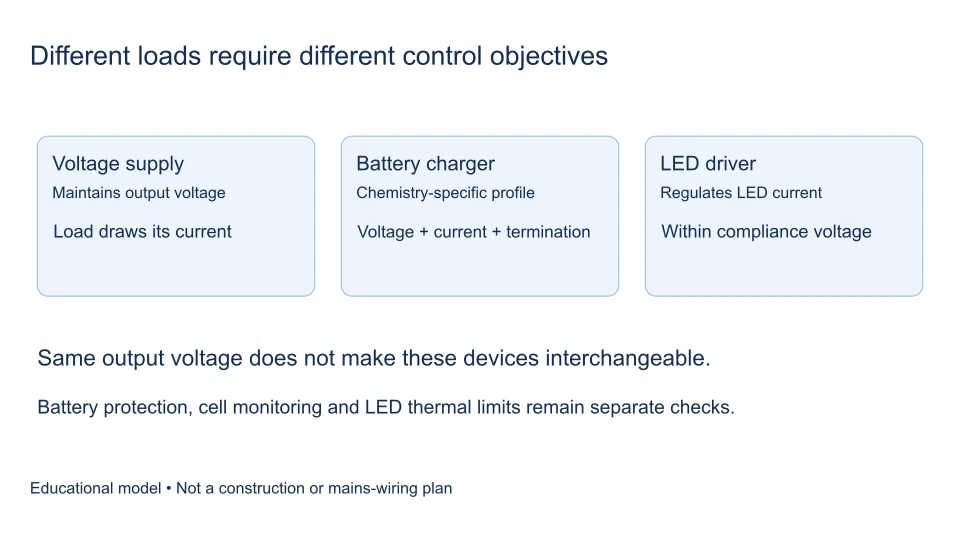
These categories can overlap inside one product. A charger may switch between current and voltage regulation. An LED product can include its own current-control electronics and accept a constant-voltage input. Describe the complete system before assigning a category from its connector or enclosure.
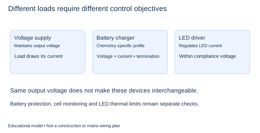
The diagram compares the control objective required by each load. It is a functional explanation, not a battery or mains connection diagram.
An AC-DC adapter supplies a rail
A regulated adapter is commonly specified by output voltage and maximum continuous current under stated conditions. In normal voltage regulation, the load determines its current demand; the adapter does not automatically force its full rated current into every load. Its overload behavior may instead involve current limiting, shutdown, or restart operation.
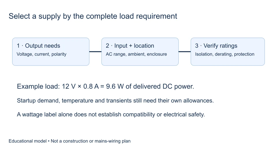
For example, a hypothetical 12 V, 2 A supply has a nominal 24 W output rating. That number does not establish connector polarity, transient capability, compatibility with a battery, or permission to exceed a device’s input rating. Our guide to why voltage does not determine available DC current explains this distinction without assuming an ideal unlimited source.
A charger manages a changing energy-storage load
A battery’s state changes during charging. Safe charge control depends on its chemistry, cell arrangement, permitted current, temperature, and operating condition. Charging may involve preliminary checks, controlled-current operation, controlled-voltage operation, and a defined completion or maintenance policy. The correct sequence and thresholds come from the battery and charger specifications, not a generic converter formula.
Texas Instruments’ battery-charging application note discusses charging methods and the importance of matching the method to the battery. Its examples should not be treated as universal settings for other chemistries or cell counts. In particular, a protective battery-management circuit does not automatically turn an arbitrary DC source into a correctly controlled charger.
The wall adapter and the cell charger can be separate
A portable device may accept power from a USB or other DC adapter, then use internal electronics to manage the battery and the device’s operating load. The external source supplies energy; the internal charger controls how much reaches the cells and when. USB power negotiation, where applicable, is another interface requirement rather than a substitute for cell-level charge management.
TI’s charger-system overview separates the DC input source from charging functions. This explains why replacing a damaged adapter requires matching the device’s documented input and interface, while replacing its battery-charging electronics is a different engineering problem. Do not infer either requirement from an AC input label alone.
Bare LEDs usually need controlled current
An LED’s forward voltage varies with current, temperature, and device variation. A small voltage change can produce a much larger current change, so treating a bare LED string as a fixed resistance can give a misleading result. A constant-current driver controls current while its output voltage adjusts within a specified compliance range.
TI’s LED-driver considerations explains why current control helps stabilize LED operation. The driver must still accommodate the actual string voltage and fault conditions. “Constant current” does not mean its output voltage is unlimited, nor does it guarantee that any number of series LEDs will work.
A voltage-fed lighting product is a different load
Some LED strips, lamps, or modules include resistors or local current regulation and are designed for a specified constant-voltage source. Other LED assemblies require an external constant-current driver. Both may be advertised as LED lighting, so the load manufacturer’s interface specification is decisive.
TI’s LED power-supply design overview includes both current-regulated and voltage-regulated architectures. When reading a label, look for the required output mode as well as voltage, current, and power. A fixed-voltage rating on a finished lighting module does not describe the behavior of the individual semiconductor LEDs inside it.
Work through current and power without inventing compatibility
Suppose an illustrative LED string is specified for 0.35 A and its expected operating voltage spans 18–24 V. Its electrical load power spans approximately 6.3–8.4 W because P = VI. A suitable current-control stage would need to cover that voltage range at the required current, along with its other specified limits. A 24 V constant-voltage adapter alone does not establish the string current.
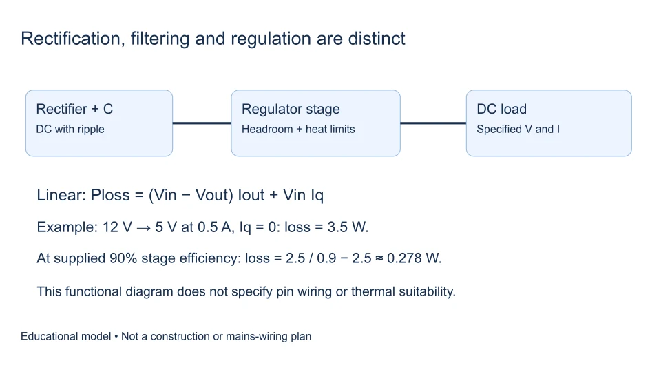
Separately, consider a hypothetical downstream controller delivering 10 W at an assumed 90% efficiency. Its input power would be 10/0.90 ≈ 11.11 W, before other system loads. That is a power-budget example, not a measured efficiency or a charger recommendation. Account for the actual controller’s input range, losses, and operating conditions instead of assigning a convenient percentage to an unknown product.
Automotive and EV systems contain several conversion stages
In a conventional vehicle, the alternator produces AC that is rectified for the vehicle’s DC electrical system. Electronics connected to that bus must also tolerate the specified electrical environment. TI’s automotive application brief discusses alternator-related supply variation and ripple. An ordinary bench adapter rating does not demonstrate automotive transient suitability.
EV charging introduces another distinction: an AC charging interface supplies AC to the vehicle’s onboard conversion system, whereas an external DC charger performs conversion before its DC connection to the vehicle. The DOE charging-infrastructure explanation distinguishes these paths. The complete charging system coordinates current, voltage, communications, isolation, and protection. A rectifier-output estimate cannot validate a charging installation or battery-pack interface.
Solar power does not start as AC
Photovoltaic modules generate DC. Grid-connected solar systems commonly use an inverter to produce AC; battery-storage systems can include DC-DC conversion or bidirectional stages. AC-to-DC conversion may appear when charging storage from an AC source, but it is not the intrinsic function of a solar panel.
The U.S. Department of Energy’s power-electronics explanation distinguishes those conversion directions. This matters when comparing products called solar chargers, inverters, and power supplies: their input source and control responsibilities can be entirely different despite a shared battery connection.
Frequently asked questions
Can a current-limited bench supply charge a battery?
Current limiting alone does not establish the correct charging sequence, temperature supervision, termination, or fault handling. Use a charging system approved for the particular battery; do not improvise settings from this comparison.
Does a smooth DC reading prove the right output?
No. A meter reading cannot establish transient behavior, isolation, charging control, or current regulation. Measuring rectifier output explains why even voltage readings need a defined measurement convention.
What can the AC-to-DC calculator tell me?
The calculator estimates supported circuit quantities under stated assumptions. It does not certify a charger, driver, adapter, or installation. Start with the load’s documented interface, identify which stage regulates it, then check the complete source-and-load system. That sequence is more reliable than matching a single number printed beside a DC symbol.
Filed under power supply concepts